Part I - Intro
Part II - Lights & Locks
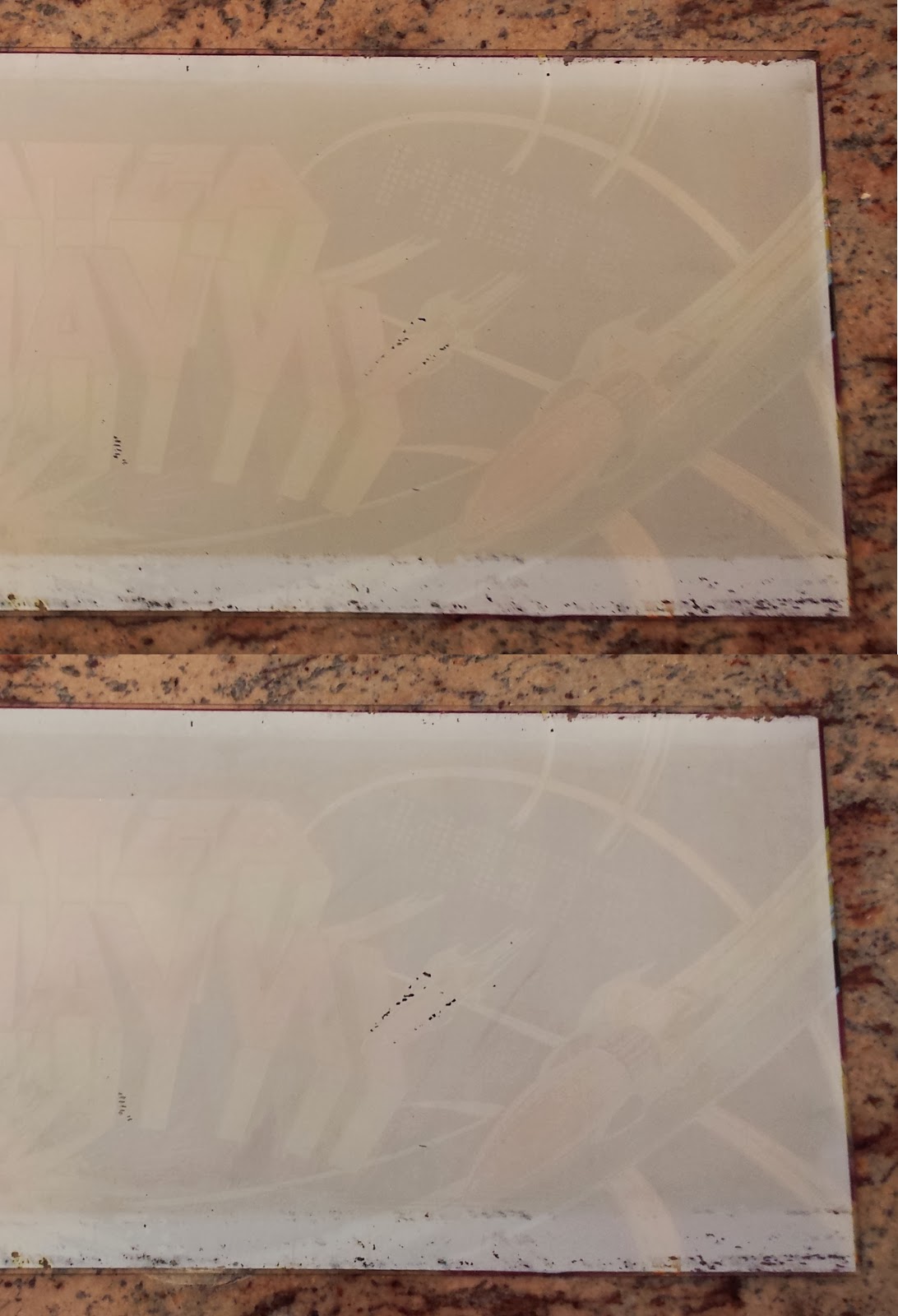
Part III - Marquee Paint
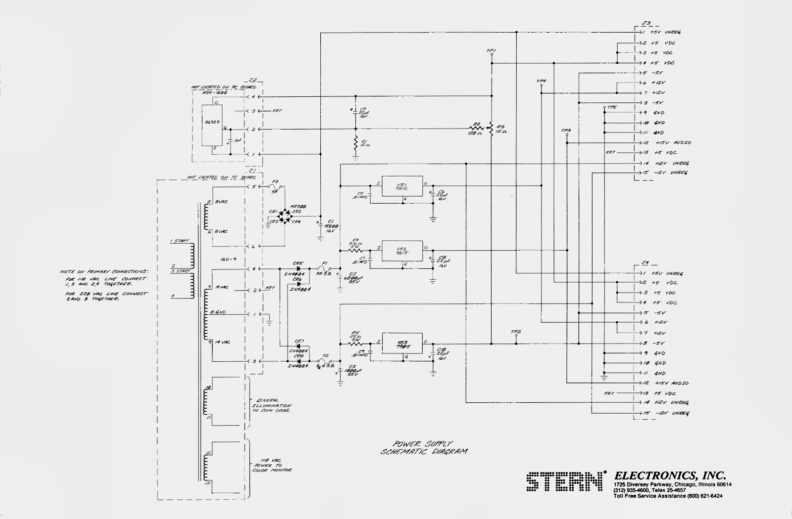
Part IV - Power Supply Rebuild
 |
| circuit boards in "card cage" |
Now that the game is working, I want to make sure it is working as well as it possibly can. Decades of dust and corrosion on the circuit boards, pots, and IC pins can lead to sub-optimal performance. I'm not sure if it will help, but it certainly can't hurt to give everything a good cleaning.
 |
| (L to R) video, CPU, & sound boards |
I started by pulling out the card cage containing all of the circuit boards. I sprayed each with circuit cleaner and scrubbed them with a soft toothbrush. Any IC's that could be removed were worked back and forth in the sockets to clean the pins. There are 8 exposed potentiometers on the sound board. One is the master volume and then I believe each game sound has it's own volume control. I marked the position of each one with a silver Sharpie before cleaning . Then they were sprayed with contact cleaner/lube and worked back and forth. I found a capacitor and resistor whose leads were touching and perhaps causing problems. I corrected that and checked for the same problem on the rest of the components. I finished up by cleaning the board contacts with 0000 steel wool. As I worked I looked closely for any signs of failing components. Everything looked good. I blew the boards dry with compressed air, cleaned the card cage and put it all back together.
 |
| someone didn't want to find an adapter for the ground plug |
 |
| cracked power cord |
While I was at it, I changed the power cord. The ground pin was broken off of the plug and the cord was starting to crack. I was going to pick up some 3 lead cable and make my own power cord. But buying wire by the foot is expensive. So instead I purchased an extension cord. With the plug molded in, the cord looks more professional anyway.

I kept the cord 11 feet long, like the original. I just cut off the female end and wired the cord to the connector with some new female crimp terminals. I kept the original warning card in place and added a zip-tie as a strain relief. The new power cord is much heavier duty than the original. In fact, if I were doing it again, I would probably go with 16 gauge wire. It was hard getting the 14 gauge wire into the connector. But this will stand up to years of hard use.
 |
| new cord in place |
Luckily the game still works and it seems like the sound is less scratchy than before. The game also used to have a few errant pixels lit up on the screen during game play. That seems to be gone as well. Next up I'll pull out the control panel and restore that.

PS - I didn't even waste the cut portion of the extension cord.
Extension Cord $15.96